“Automatic transmissions are the choice of drivers.
Manual transmissions might survive only in some sports cars.”

What is an Automated Manual Transmission (AMT)?
A new transmission that adds mechanisms for automating manual clutch operation and gear shifting to a conventional manual transmission.
If we realize the new challenge, we can outperform ours competitors.
Right after the new AMT project kicked off, the team faced a hard choice between two control platforms: hydraulic or motor control. Technologies in the hydraulic automatic clutch system (ACS) developed earlier might be suitable but would make the new transmission bulky and costly.
Motor control would downsize the transmission and reduce cost, but no expertise in development was available. At that time, the team heard an unexpected announcement from Europe.
In 1998
DaimlerChrysler released a new model under its Smart brand, with the world’s first automated manual transmission with electric motor control. That news knocked them stupid. The members immediately analyzed the information and found it to be about a compact automated manual transmission packed with state-of-the-art tech-nologies. It spurred the spirit of the project members.
“We are shooting for a motored automated manual transmission, one that is more compact and cost-effective. Our challenge is going to be something very new to us. But, once it achieves the responsiveness of a hydraulic transmission system, it will outperform DaimlerChrysler’s….”
In January 1999
Advanced development started, aiming at a third variation of automotive transmission – dubbed an “Automated Manual Transmission” – that would integrate the fuel efficiency of MTs and convenience of ATs.
Challenges to further downsizing – reproducing the touches of human clutch operations “The biggest challenge is how to downsize.”
The question was reasonable enough. Clutch discs wear and lead to load variations, as they are in-service for years. In other words, increasingly more force is needed for clutch operation.
In a typical manual transmission, the driver engages/disengages the clutch according to the response of the clutch pedal as shown in the figure below. An electric-motor-equipped AMT does not allow manual «control» that drivers perform naturally.
The motor must be capable of engaging/disengaging the clutch even when the clutch disc is nearly worn.
If the motor performs poorly, the force will come up short as the wear advances, possibly causing the clutch not to engage/disengage.
However, a motor with the capacity designed for a worn disc could be bulky and waste generated power or waste of energy??
How could the team best solve this problem?
They came up with a «load controller» that would allow stable clutch operations with a small motor.
Located inside the clutch cover, the device was designed to maintain load variations within a certain safe range. Therefore, a large motor would not be required. “All right. Now, we have to come up with a way to keep loads constant….”
“Here’s another thing. How could we know the degree of wear in the disc?”
These newly raised challenges kept the project team members busy, looking for ways to design a load control cover (LCC).
How a clutch works?
The clutch uncouples the engine from the wheels when the gears are changed.
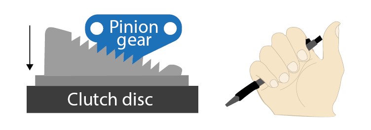
It is the same mechanism as a retractable pen that might be needed.
The team explored ways to maintain load variations within a constant range. Meetings were held one after another to look for the best answer. Though, a clue did not come quickly. Hundreds of memos were piled up on desks….
Everyone was a bit frustrated. But, then, in the middle of one of those meetings, someone was clicking a retractable pen again and again when, out of the blue, a voice was heard, “That might be what we need.”
No one else understood what he was talking about, but he continued, “The ratchet, I mean, the clicking mechanism of the pen is the solution we have been looking for.” His idea was applying the ratchet, like the one in retractable pens, to a load controller. A retractable pen comes with a quick, retractable button for sliding the ball-point filling in and out. A simple ratchet mechanism employs the combination of a spring and the repeated locking, fixing and release of angled teeth, to push the ballpoint tip into place outside of the casing. The click on the button slides the tip out, and the tooth locks it.
Another click releases the tooth and the spring pulls the tip back into the casing. “We can apply the force of the clicking, the locking by the teeth, and sliding movement of the spring.”
As shown in the figure below, using the mechanism of the rack and pinion engagement slides the pinion gear, according to the wear in the clutch disc, so that load variations are kept within a constant range.
Already in their mind, a prototype was within striking distance.
The test vehicle will not start! The team’s gamble backfires…
January 2002
Marked a series of test-runs on a final prototype but saw the team abruptly encounter trouble.
The load controller stopped moving whereby bringing the test vehicle to a stop.
The cause was immediately identified.
Tight budget had made the team decide to take a gamble — a significant change had been made to the whole structure of the auto-mated manual transmission in the final prototyping phase. The team was working under a tight deadline.
Time constraint forced them to rush through three phases that should have been done in consecutive order, i.e., theoretical analysis in design, testing with a chassis dynamometer, and on-vehicle data collection.
Results of the data analysis were not yet available for the prototype test drive, and tests were run with strict parameters. One day, temperatures much higher than experimentally allowed, coupled with the presence of water and dust during a trial run, caused the on-vehicle LCC to break down.
The chief of the development project team said, “It’s no use crying over spilled milk. To monitor the system as a whole requires more than a simple data analysis of the prototype. We need to build a system that monitors the whole thing.”
The team incorporated a systematic approach for digitally monitoring changes on the LCC and the AMT under different conditions. They quickly took action, for example, to increase spring load for greater control stability, adopt a dust-proof structure, and change the material of the spring. Two months flew by. Better fuel economy than manual transmissions; More cost competitive than automatic transmissions.
The finished prototype was showcased and tested not only in Japan. It took a tour to Germany and Spain for on-vehicle testing.
It was something unusual for an automotive parts supplier in Japan to conduct full-scale vehicle tests in European markets.
Testing seemed to never end, as tests were repeated one after another on Aisin’s proving grounds in Toyokoro, Hokkaido, and Fujioka, Aichi, as well as on public roads.
“Went the distance of 100,000 km!” Shortly thereafter reports came in one after another.
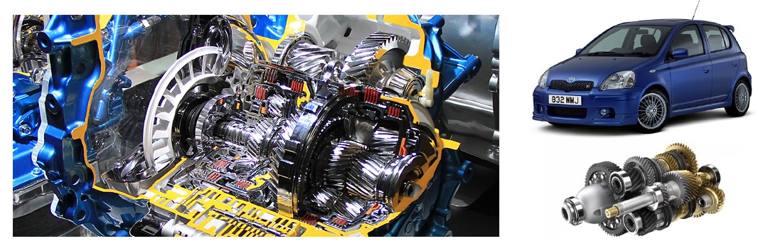
Spring, 2003
The first Toyota Yaris equipped with Aisin’s automated manual transmissions was born. The Toyota Corolla Verso launched in 2004 had an AMT with additional features.
It had an AMT with features that added the fun of driving via a Sports Mode to the conventional normal auto mode. The AMT has become the transmission of choice for the Corolla Diesel and Yaris Diesel made by Toyota Motor Corporation, Suzuki’s Swift, and more.
Cars with electric motor automated manual transmissions from Aisin were proven to offer about 4% better fuel economy than those with typical manual transmissions, while, at the same time, were more reasonably priced than fully automatic transmission cars.
Performance-wise, the vast majority of the goals set at the project start were achieved.
The team members are already in the pursuit of a new mission : “Creating a genuinely innovative automated manual transmission that goes far beyond any MT.”